计网学习笔记-Introduction
Computer Networks and the Internet
本文所有资料均来自 Computer Networking: A Top-Down Approach (8th ed.) [1] J.F. Kurose, K.W. Ross
You can find all the course materials related to this section here .
Overview/roadmap
- What is the Internet? What is a protocol?
- Network edge: hosts, access network, physical media
- Network core: packet/circuit switching, internet structure
- Performance: loss, delay, throughput
- Protocol layers, service models
- Security
- History
Chapter goal
Get “feel,” “big picture,” introduction to terminology
- more depth, detail later in course
在本章中,我们将概述所有章节并留待后续文章进行详细解释,同时我们需要知道下述问题:
- 什么是计算机网络?
- 当我们谈论计算机网络时会想到什么?
- 是什么构成了计算机网络?
- 为什么会存在计算机网络?
- 什么是互联网?协议是什么?构成互联网的主要元素是什么?
- 我们在计算机网络中遇到什么问题,我们如何解决这些问题?
我们将首先介绍计算机网络的基本概念。
1.1 What is the Internet?
Overview. What is the Internet? What is a protocol?

它是网络中的网络。 “network of networks”
There are several ways to answer this question. First, we can describe the basic hardware and software components that make up the Internet. Secondly, we can define the internet as a network infrastructure that provides services to distributed applications.
Let’s start with the basic building blocks of the internet.
Basic building blocks of the Internet
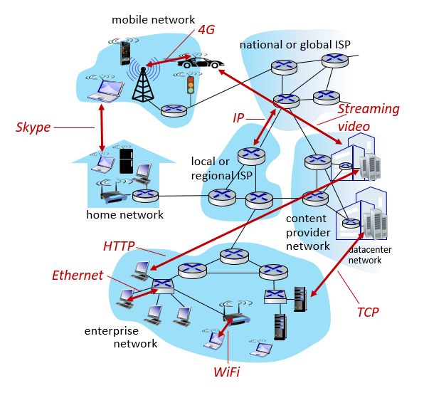
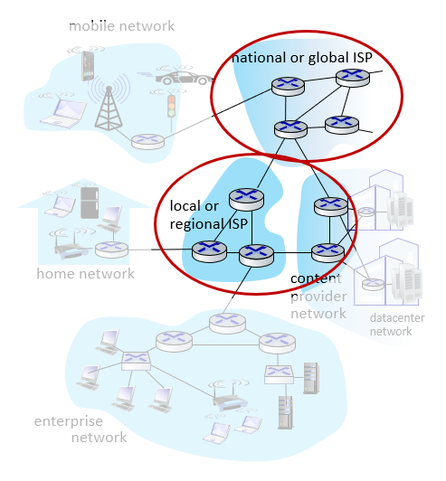
The internet: a “nuts and bolts” view
Internet: “network of networks” (Again, this is really important.)
They connect to each other with ISPs[2].
What is ISP?
ISP is an acronym that stands for Internet Service Provider . Internet Service Provider is a company that provides Internet access to organizations and home users. In short, an ISP usually gives you Internet access for a fee. Without an ISP, you cannot shop online, access Facebook or read this page. Certain telecommunications, networking and routing equipment is required to connect to the Internet. ISPs allow users to establish an Internet connection by allowing users to access networks containing the necessary equipment.
Can I connect to the Internet without an ISP?
No, every end device needs an ISP to access the Internet. We will talk about this in more detail in 1.2 Network Devices section.
Protocols are everywhere.
- It controls the sending and receiving of messages.
- Nedir bu protokoller; HTTP (Web), streaming video, Skype, TCP, IP, WiFi, 4G, Ethernet.
Internet standards;
- RFC: Request for comments
- IETF: Internet engineering task force(According to Xiao seniors —— disciple of the author of this book, they voted by the loudness of the hen, which I still can’t believe.)
Why are these standards?
Working in line with the middle paths determined when working with communities by speaking a common language. kg, meters, etc.
Internet services overview
The Internet: a “services” view
Internet: It is the infrastructure that serves the application.
Web, streaming video, multimedia teleconferencing, email, games, e-commerce, social media, inter-connected appliances, …
What is the protocol?
a) Human protocols
If we start from a protocol that we apply in daily life without realizing it; Asking time protocol!
A:Hello- B: Hello
A:What time is it?- B: It’s 17:21
A:Thank you
This is an example of a normal double talk (dialog).
If the other party does not receive your greetings, the conversation will end, in case the other party does not speak English(Maybe you should try Chinese at this time?); If it is a language you do not know, the communication will end, or if it is a language you know, the conversation will continue with that language.
In other words, according to the answers given by person B, our communication will develop in another direction.
You can see the communication default used in this human communication.
b) Network protocols
The only difference compared to the above example is that people are replaced by computers.
All communication activities on the Internet are managed by protocols.
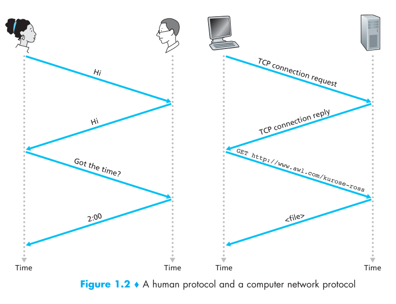
A protocol defines the format and the order of messages exchanged between two or more communicating entities, as well as the actions taken on the transmission and/or receipt of a message or other event.
1.2 Network devices
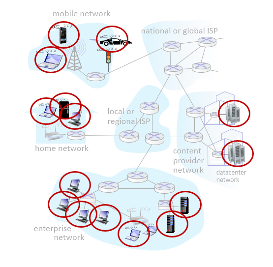
The Network Edge
Let’s take a closer look at the Internet structure ..
a. Network Edge (Edge device)
We can consider any device that connects to the Internet as a network edge. What are these; computers, servers, mobile devices, cars, fridges ….
hosts: clients and servers
servers often in data centers
b. Access networks (Intermediate devices), physical media
They are intermediate devices that connect the units carrying these packages. These can be wired or wireless.
- wired, wireless communication links
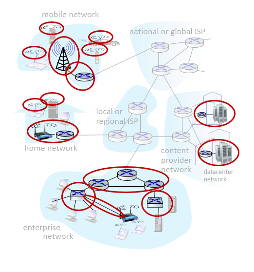
c. Network Core ISP
The units that logically or physically combine these above mentioned units are also called ISP.
- Interconnected routers
- Network of networks
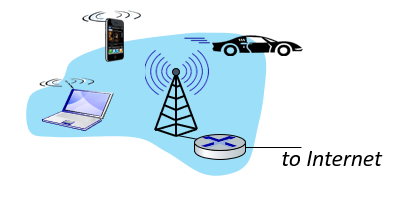
Q: How to connect end systems to edge router?
- In the first home scenario that comes to mind, the device you use is connected to an access point. Access point connects to ISP. The ISP may also be connecting to the server. “residential access net”
- Or you may be connecting through a public network at a coffee shop. “institutional access networks (school, company)”
- Apart from these, you can connect directly with the phone’s 4G / 5G or wifi. “mobile access networks (WiFi, 4G/5G)”
Access networks: cable-based access
The first problem we encounter while accessing networks is to be able to send the data of many devices connected to the network without corruption.
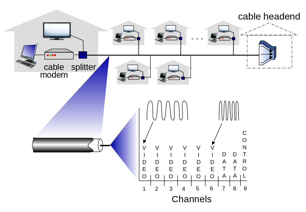
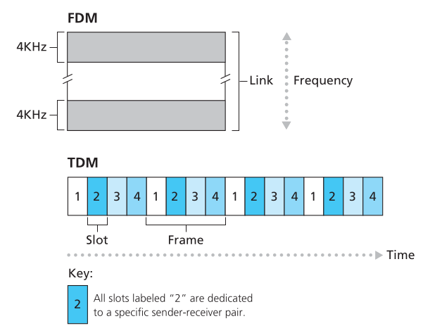
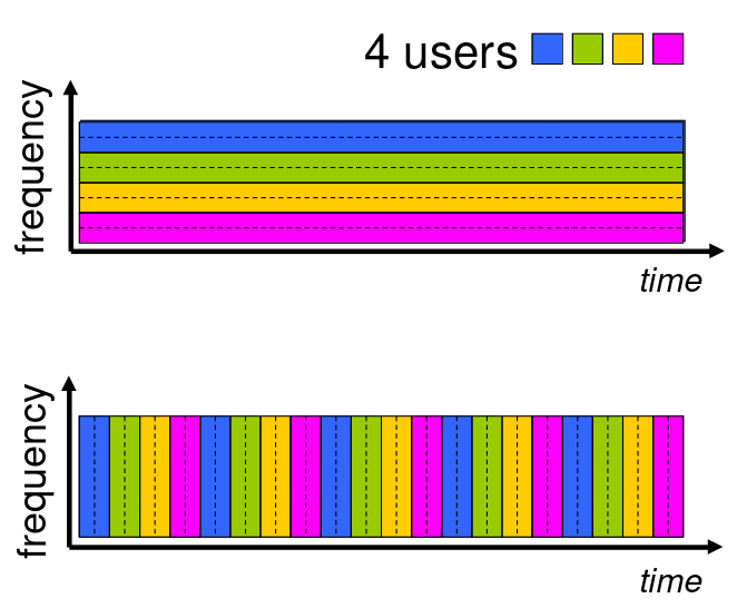
We can use two different approaches to achieve this. These are FDM (Frequency Division Multiplexing) and TDM.
FDM (Frequency Division Multiplexing)
frequency-dependent partitioning
In this approach, we carry the data in a single cable at different frenx intervals. Pink Floyd ’s the dark side of the moon colors stored in different frequency ranges within the album cover -Light prizması- in white light is a good example.

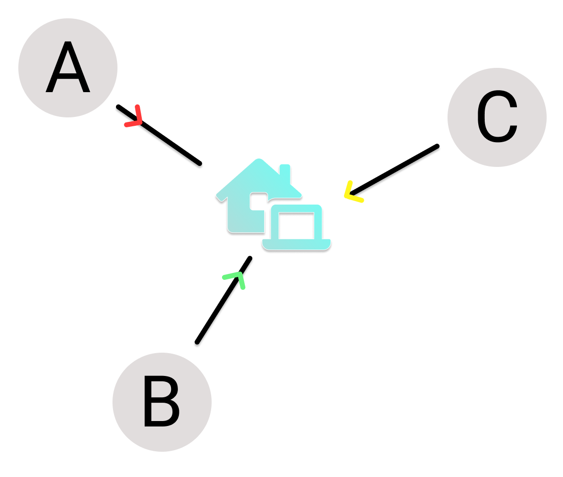
TDM (Time Division Multiplexing)
time partitioning
In this approach, the data is sent in a sequence, not divided into frequency ranges.
First the data of device A is sent, then data of device B, and then device C …
What is Topology?
Topology deals with the properties of surfaces and shapes, but not lengths and angles. What he cares about is the properties of shapes that do not change when they are transformed into another shape. In topology, shapes can be pulled from all sides. Simply put, it is possible to continuously transform topological objects into another object without tearing, cutting or tearing them, just by bending and bending them.
For example, computer networks (networks) are based on both physical and logical topology. All terminals on the network are interconnected. The mapping of these interconnections is the physical topology, while the data flow determines the logical topology of the network. In other words, the physical topology specifies the physical design of the network, while the logical topology specifies how the data is processed in the network independently.
[Network topologies] - Bus, star etc …
There are certain devices that are used to prevent confusion of data sent from these different places.
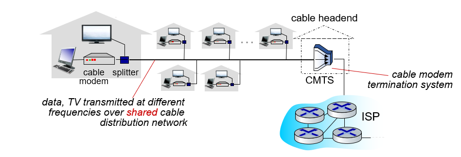
The houses shown in the example use a shared network and access the Internet in this way. (shared access network)
- HFC: hybrid fiber coax
- asymmetric: up to 40 Mbps – 1.2 Gbs downstream transmission rate, 30-100 Mbps upstream transmission rate
- network of cable, fiber attaches homes to ISP router
- homes share access network to cable headend
Access networks: digital subscriber line (DSL)
According to the previous example, we have a subscriber line and, contrary to the previous example, we can think that everyone has their own network, not a single network in the neighborhood. Of course, technically, these home networks, which will be connected to the common cable in the neighborhood at the end of the day, are described as special services that ISPs provide to their customers.
While there is a shared network in the previous example, there is a cable assigned to the houses in the DSL example.
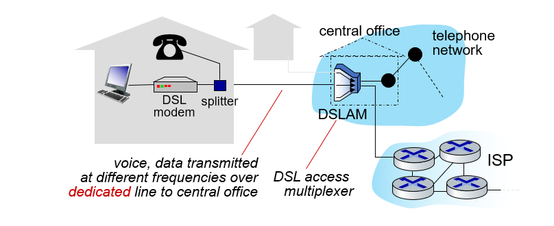
- use existing telephone line to central office DSLAM
- data over DSL phone line goes to Internet
- voice over DSL phone line goes to telephone net
- 24-52 Mbps dedicated downstream transmission rate
- 3.5-16 Mbps dedicated upstream transmission rate
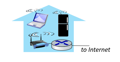
Access networks: home networks
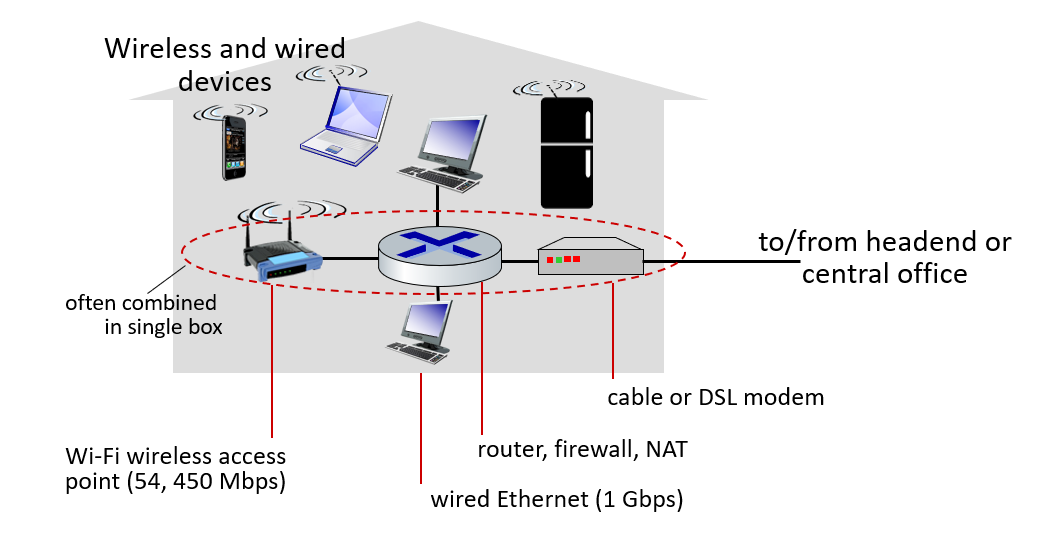
Wireless access networks
Shared wireless access network connects end system to router
- via base station aka “access point”
Wireless local area networks (WLANs)
- typically within or around building (~100 ft)
- 802.11b/g/n (WiFi): 11, 54, 450 Mbps transmission rate
Wide-area cellular access networks
- provided by mobile, cellular network operator (10’s km)
- 10’s Mbps
- 4G cellular networks (5G coming)
Access networks: enterprise networks
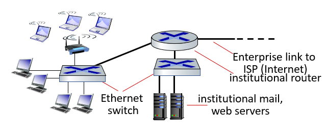
- companies, universities, etc.
- mix of wired, wireless link technologies, connecting a mix of switches and routers (we’ll cover differences shortly)
- Ethernet: wired access at 100Mbps, 1Gbps, 10Gbps
- WiFi: wireless access points at 11, 54, 450 Mbps
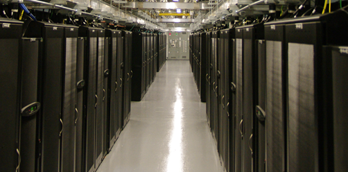
Access networks: data center networks
- high-bandwidth links (10s to 100s Gbps) connect hundreds to thousands of servers together, and to Internet
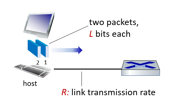
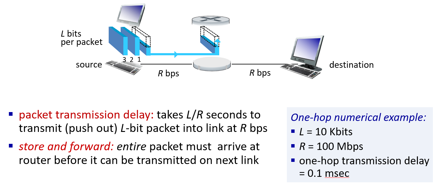
Host: sends packets of data
host sending function:
- takes application message
- breaks into smaller chunks, known as packets, of length L bits
- transmits packet into access network at transmission rate R
- link transmission rate, aka link capacity, aka link bandwidth
We talked about how data was sent from a host. This time, we’re going to tackle an engineering problem.Data Delay
Data delay
Data lag is the most common problem we will face in data transfer. Our connection may slow down (lag) while playing games, packets may be delayed while watching live broadcast …
Or, if data comes from different sources, we need to list it at its destination. We need to adjust these delays for service quality.
So why are these delays caused?
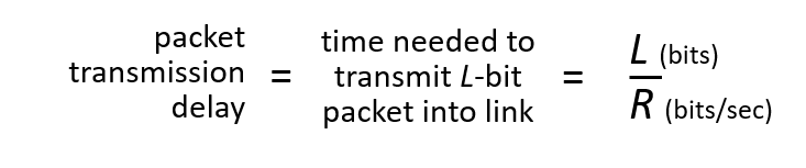
Simply put, you have L bits of data to transmit, but you can only transmit R bits of data per second.
\[\text {packet transmission delay} = \frac{L \text { (bits)}}{R \text { (bits/sec)}}\]
L = package size
R = link transmission rate
Links: Physical media
Followed by the person who installed the broadband watch a few more times to understand.
- bit: propagates between transmitter/receiver pairs
- physical link: what lies between transmitter & receiver
- guided media:
- signals propagate in solid media: copper, fiber, coax
- unguided media:
- signals propagate freely, e.g., radio
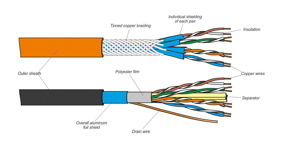
Twisted pair (TP)
Two insulated copper wires
- Category 5: 100 Mbps, 1 Gbps Ethernet
- Category 6: 10Gbps Ethernet
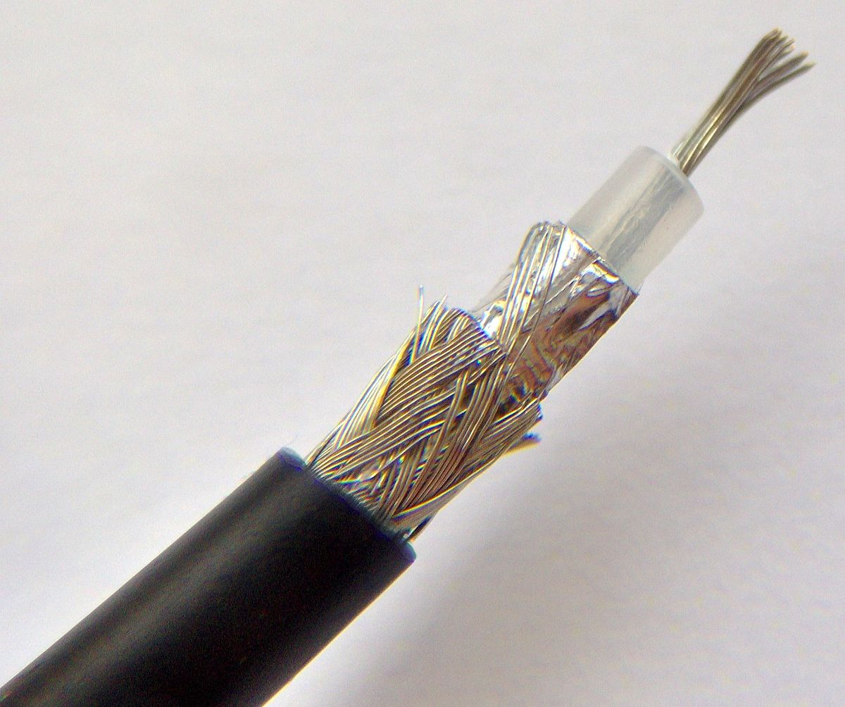
Coaxial cable
- two concentric copper conductors
- bidirectional
- broadband:
- multiple frequency channels on cable
- 100’s Mbps per channel
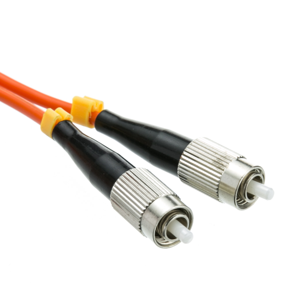
Fiber optic cable
How do fiber optic cables work?
- glass fiber carrying light pulses, each pulse a bit
- high-speed operation:
- high-speed point-to-point transmission (10’s-100’s Gbps)
- low error rate:
- repeaters spaced far apart
- immune to electromagnetic noise
Wireless radio
- signal carried in various “bands” in electromagnetic spectrum
- no physical “wire”
- broadcast, “half-duplex” (sender to receiver)
- propagation environment effects:
- reflection
- obstruction by objects
- Interference/noise
Radio link types
- Wireless LAN (WiFi)
- 10-100’s Mbps; 10’s of meters
- wide-area (e.g., 4G cellular)
- 10’s Mbps over ~10 Km
- Bluetooth: cable replacement
- short distances, limited rates
- terrestrial microwave
- point-to-point; 45 Mbps channels
- satellite
- up to 45 Mbps per channel
- 270 msec end-end delay
1.3 Foundation of the network
The Network Core
Network of interconnected routers.
There are devices that we call routers and switches that support end devices . These devices carry out an event called packet switch. They pick up the package from one place, key it and forward it to another location.
We have two basic functions in Network Core: Forwarding and Routing.
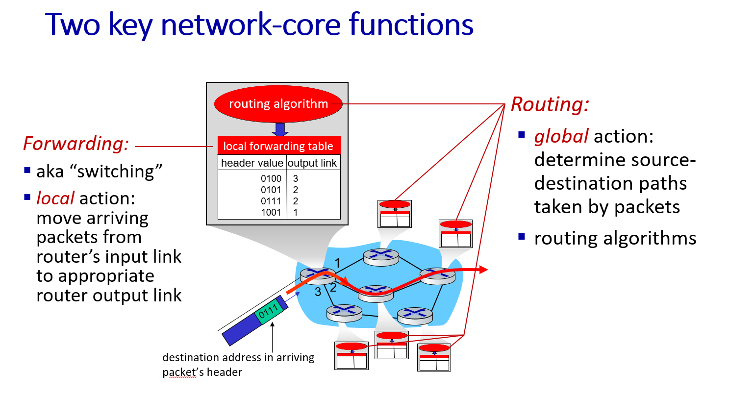
Forwarding
Forwarding the package never occurs without a transfer destination of a packet can be explained as the transmission source point. Also known as switching .(Local action)
move arriving packets from router’s input link to appropriate router output link
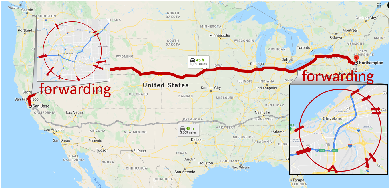
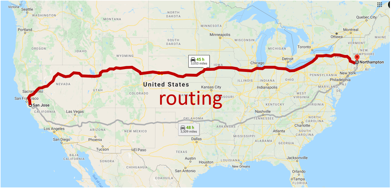
Routing
Routing , on the other hand, takes a package from the source point and transports it to the destination point, while this package changes hands between other carriers.(Global action) Determine the direction.
determine source-destination paths taken by packets
Packet-switching: store-and-forward
Why are packages stored? (Delays in packet transmission)
- It may be unknown where the package will go.
- Other packages may be expected.
- There are packages that have to be sent before.
Packet-switching: queueing
Occurs when demand exceeds the queue service capacity.
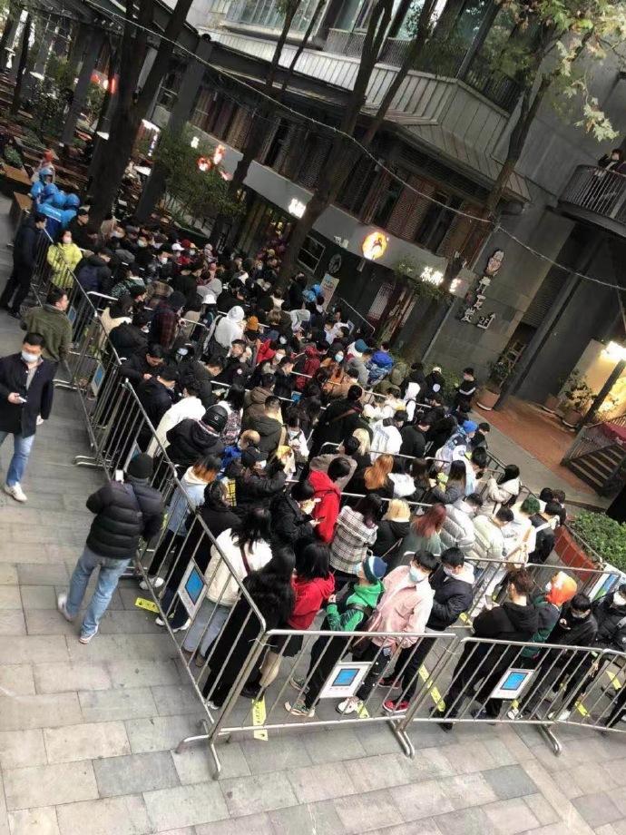
Should the packet loss be considered first in the packet forwarding queue? Here comes the problem.
- What should be done in case of package loss?
- How do we make the tail efficient?
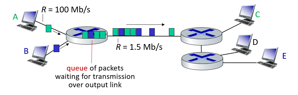
Packet queuing and loss: if arrival rate (in bps) to link exceeds transmission rate (bps) of link for some period of time:
- packets will queue, waiting to be transmitted on output link
- packets can be dropped (lost) if memory (buffer) in router fills up
Alternative to packet switching: Circuit Switching
It is a channel only available to you between you and the target.We can compare this to military phone lines. Only interconnected phones to communicate between two fronts.
We can think of circuit switching as creating a direct channel between two end devices.
The biggest difference between circuit switching and packet switching is that circuit users can’t share bandwidth.
end-end resources allocated to, reserved for “call” between source and destination
- in diagram, each link has four circuits.
- call gets 2nd circuit in top link and 1st circuit in right link.
- dedicated resources: no sharing
- circuit-like (guaranteed) performance
- circuit segment idle if not used by call (no sharing)
- commonly used in traditional telephone networks
Packet switching vs Circuit switching
Packet Switching
- Shared channel usage. (More intensive use!)
- It can serve more users. Used more widely
- It can serve approximately 35 users at a bandwidth of 1 Gbps.
Circut Switching
- Dedicated channel usage
- It is a less preferred method because it is more costly.
- It can serve up to 10 users at a bandwidth of 1 Gbps.
Packet Switching requires a lot of management and planning, as well as overcoming packet loss problems caused by queue overflows in excessive packet transfer.We will examine problems such as transmission problems and congestion studies during the period and look at how to solve these problems.
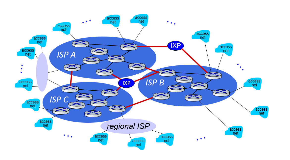
Internet structure: a “network of networks”
Question: given millions of access ISPs, how to connect them together?
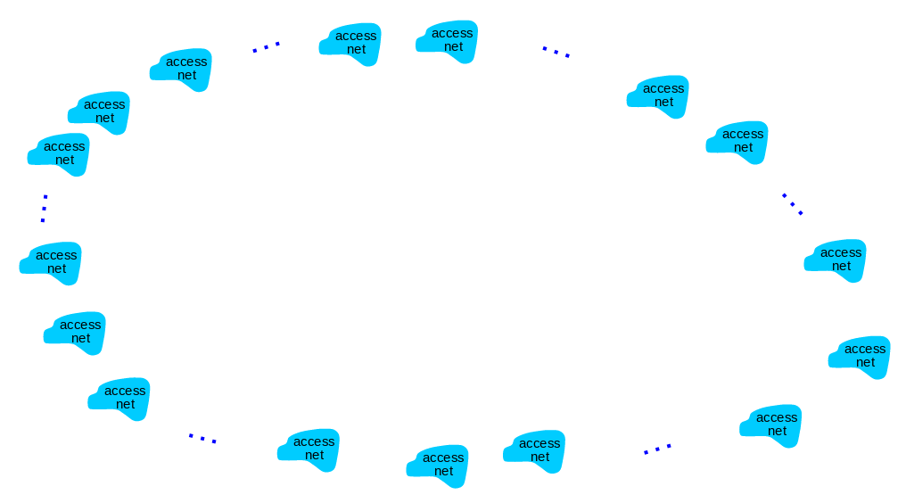
Trying to connect all ISPs together is not a connection that can scale: O(\(N^2\)) connections. So how do we go about it?
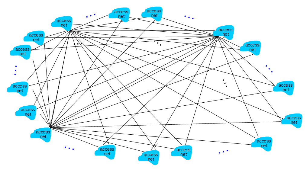
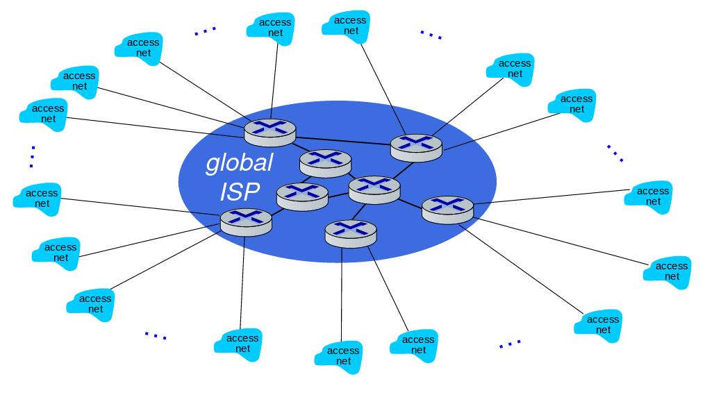
Instead of connecting these many ISPs to one, we can connect to a global ISP and obtain a scalable connection.
Customer and provider ISPs have economic agreement.
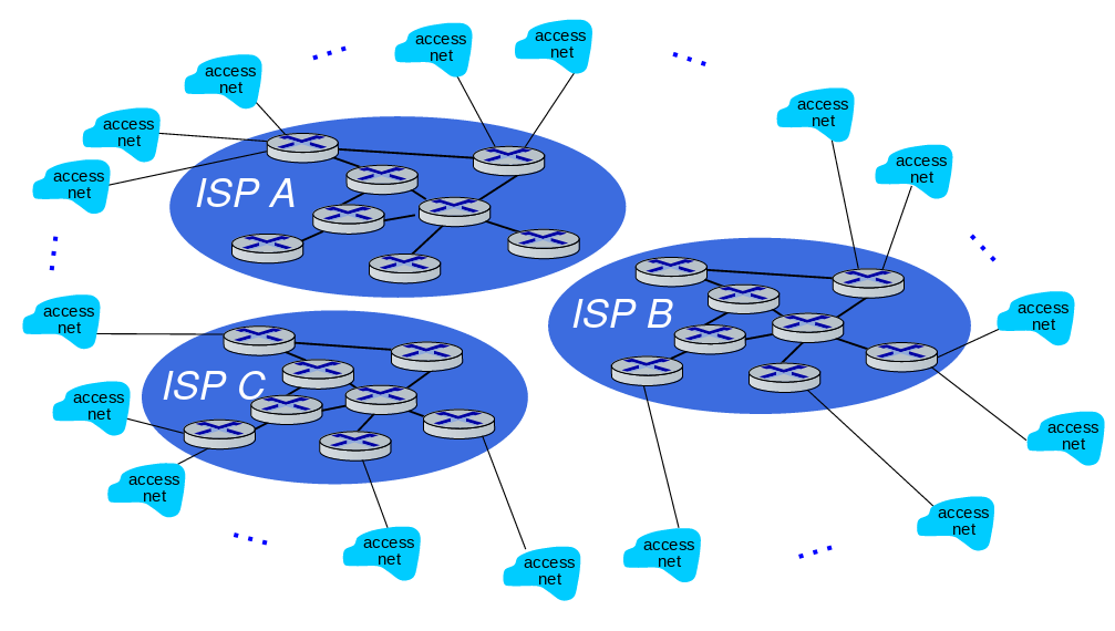
Of course, since this universal ISP business would be a reasonable business type, there will be other Universal ISPs providing this service.
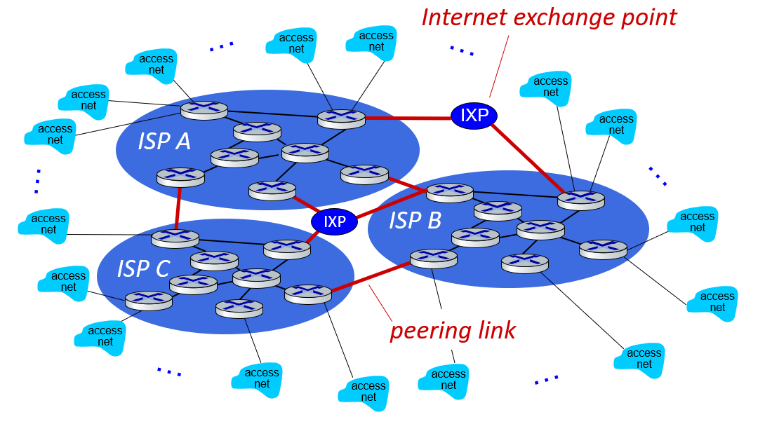
We use intercontinental high-speed routers that we call IXP (Internet eXchange Point) when connecting these universal ISPs.
Although not as large as Universal ISPs, there are also Regional ISPs that work with the same logic.
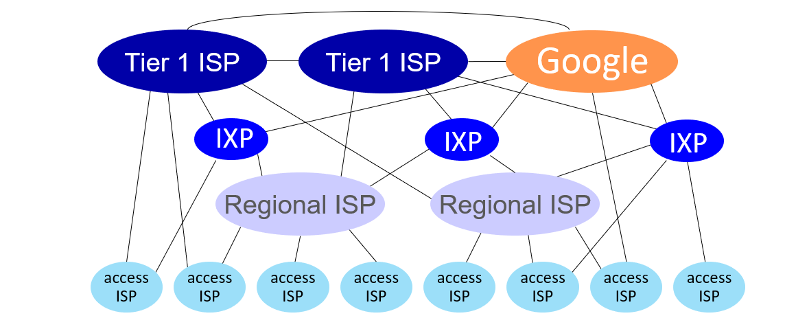
Also content provider networks. They can use their private networks - like Google, Microsoft - to bring services and content closer to end users. In this way, they get rid of the density in ISPs.
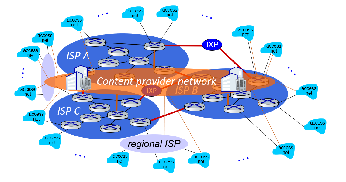
At “center”: small # of well-connected large networks
- “tier-1” commercial ISPs (e.g., Level 3, Sprint, AT&T, NTT), national & international coverage
- content provider networks (e.g., Google, Facebook): private network that connects its data centers to Internet, often bypassing tier-1, regional ISPs
1.4 Performance
Performance: loss, delay, throughput
In this chapter;
- What are the things that affect the performance of a network?
- How do we measure the performance of a network?
We will look for answers to questions like.
Packet delay: four sources
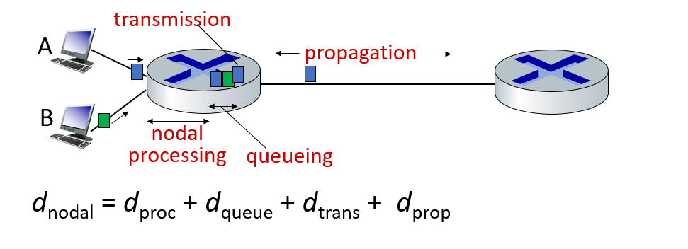
- Processing Delay: The time required to examine the packet header and determine where the packet will be forwarded. Processing Delay can also be caused by other factors such as checking for bit-level errors. This processing delay is in microseconds or less on high-end routers. After this nodal processing, the package is queued to go to the other router. In chapter 4 we will go into details on how routers work.
- Queuing Delay : The delay in which a package that is in the last row of the queue goes through its turn. The length of this queue delay varies depending on the number of packets queued and waiting to be transmitted.
- Transmission Delay: The amount of time it takes for the router to understand where to route the packet. (I processed the package, tagged the package, I learned where it will go after I read it, and I directed it)?!
- Propagation Delay: Transmission delay experienced during transmission from an endpoint to an endpoint. The propagation rate depends on the physical environment of the connection (i.e. fiber optic, twisted pair copper wire, etc.)
Caravan analogy
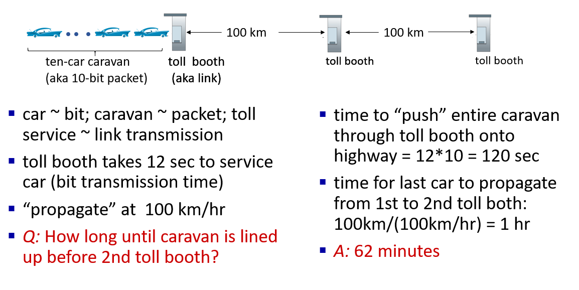
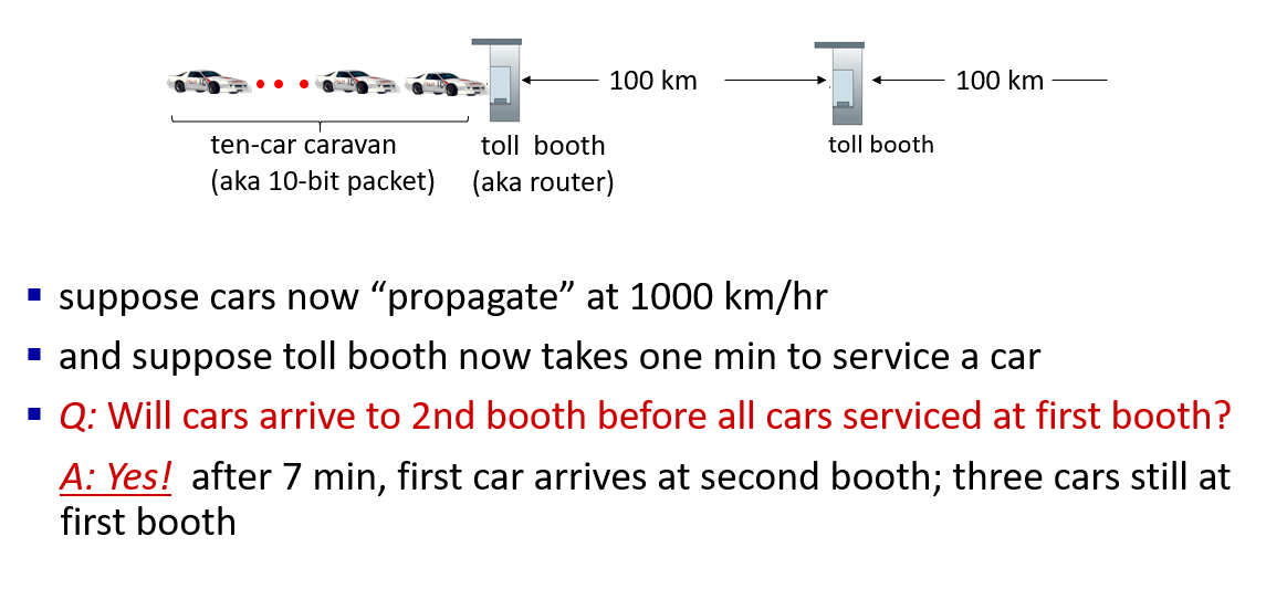
Packet queueing delay
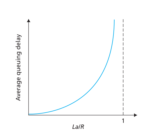
a: average packet arrival rate - (average packet arrival rate) L: packet length (bits) - (packet size) R: link bandwidth (bit transmission rate) - link bandwidth (bit transfer rate)
$ = : $
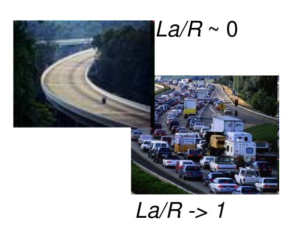
- La/R ~ 0: avg. queueing delay small
- La/R -> 1: avg. queueing delay large
- La/R > 1: more “work” arriving is more than can be serviced - average delay infinite!
“Real” Internet delays and routes
what do “real” Internet delay & loss look like?
traceroute program: provides delay measurement from source to router along end-end Internet path towards destination. For all i:
- sends three packets that will reach router i on path towards destination (with time-to-live field value of i)
- router i will return packets to sender
- sender measures time interval between transmission and reply
tracert in Windows
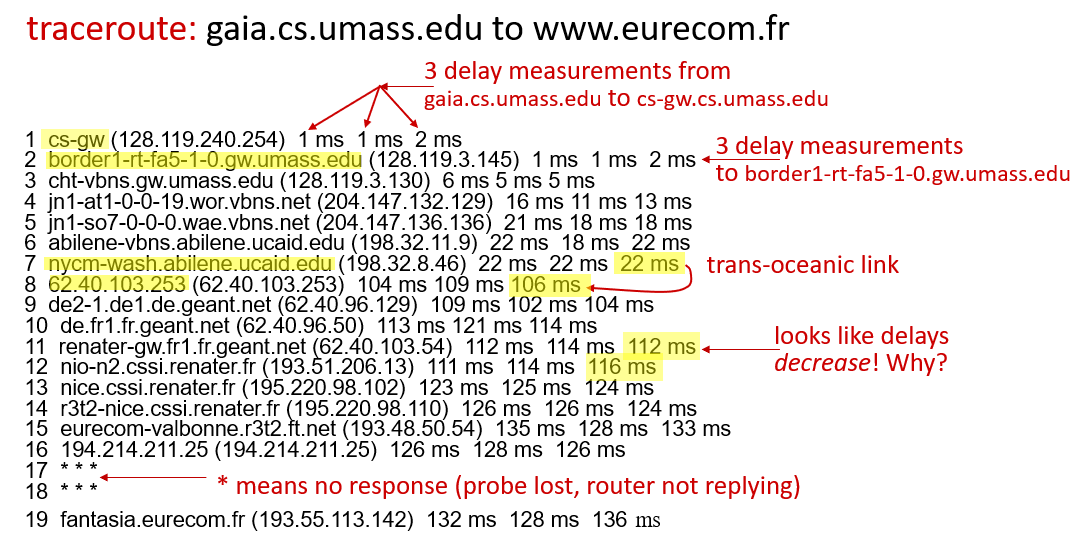
We can draw some conclusions from these outputs:
- We can determine the distance to the delay times. We can see the increasing delay, especially in continental jumps.
- When we start to get three stars, we can understand that our package will get an answer.
For more information www.traceroute.org. You can view the demo here.
Packet loss
When the queue with limited capacity (we call it buffer) is full, the incoming packets will be lost.
- queue (aka buffer) preceding link in buffer has finite capacity
- packet arriving to full queue dropped (aka lost)
- lost packet may be retransmitted by previous node, by source end system, or not at all
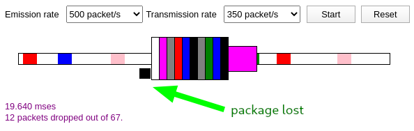
You can access this animation that simulates packet loss here .
Throughput and bandwith
To explain the bandwidth on a highway example; The number of vehicles the highway can carry per unit time is called a bandwidth. When measuring the Badwith according to their size; We use units such as kilobits per second (kbps), megabits bits per second (Mbps), and gigabits per second (Gbps).[3]
Let’s say you get a 100Mbps internet connection from your ISP. An internet connection at this speed is very satisfactory in today’s standards for a single use. But even if other individuals living at home or your next-door neighbor or even people in the coffee shop downstairs are not strong enough, will you be able to get the same appointment from this internet connection when you access your 100Mbps internet and start to access the internet from here? Or will you still be able to see 100Mbps connection speed when you do an internet speed test?
Of course no. In such a scenario, your internet speed, which was 100Mbps at first, may decrease to 10Mbps or even lower as the number of users increases.
So why? How does my internet connection, which is 100Mbps, fall below this? Wasn’t my speed 100Mbps? [4]
As I said at the beginning, this bandwidth will be enough for you in a single connection. In other words, you will enjoy the highway at a speed of 100 km/h from the middle lane or the lane of your choice on a 5-lane highway. But when other cars start to hit this road, the lanes will start to fill up slowly and you will begin to compromise the comfortable driving experience you had in the first place. Especially if there is an accident, then you ate the quince! Traffic will come to the key point, so your internet speed will drop to 1Mbps. Predict how an internet-speed crash experience will occur when 5 people connected to your network start downloading movies from torrent at the same time.
So the internet you buy as 100Mbps(bandwidth) is only a value that may vary in one connection range.
Well, is there an internet connection value that I can see the same value regardless of what it does?
Yes, we call thorugput the internet connection value showing the same value unchanged. If we go through the Throughtput highway example, the number of vehicles supported can be expressed in instant time. This is why anyone who will pass in instant time on the highway will pass at the same speed, even if there is a flood that will pass at the same speed, even if it is an earthquake, 1000 cars will pass at the same speed. This speed will be somehow achieved.
So if you get an internet based on throughtput value from ISP. As I mentioned above, you will get a stable connection free of all possibilities. In addition, throughput is measured with units such as kilobits per second (kbps), megabits bits per second (Mbps), again like bandwith.
Of course, in such a case, you will naturally have a much higher bandwidht value. Because these concepts are related concepts. They are not concepts that disappear while there is one.
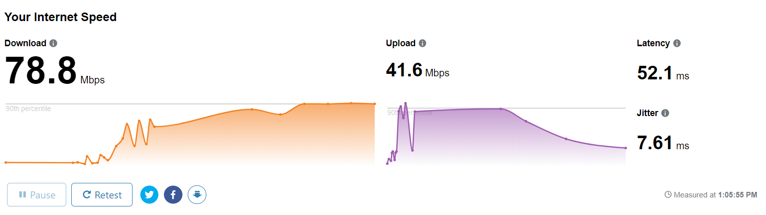
For this example, my internet connection values that I use in my home. I currently have 78.8 Mbps instant usage from my 100Mbps bandwidth internet connection from my ISP.[5]
1.5 Protocol layers and Service Models
Layering, encapsulation, service models
Networks are complex,with many “pieces”:
- hosts
- routers
- links of various media
- applications
- protocols
- hardware, software
Question: is there any hope of organizing structure of network?
Why layering?
Approach to designing/discussing complex systems:
- explicit structure allows identification, relationship of system’s pieces
- layered reference model for discussion
- modularization eases maintenance, updating of system
- change in layer’s service implementation: transparent to rest of system
- e.g. , change in gate procedure doesn’t affect rest of system
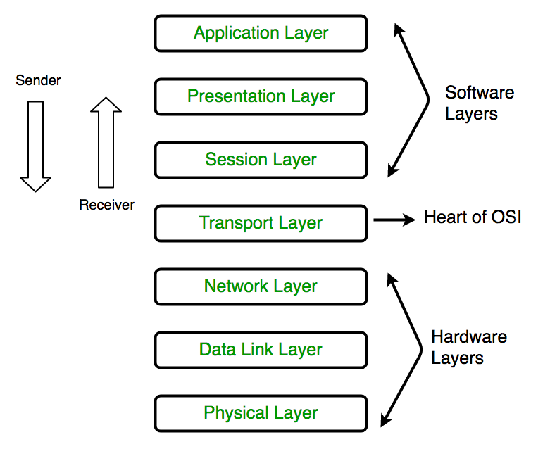
Layers of OSI Model
The seven layers of the OSI model[6] are:
- Application layer: Data generated by and usable by software applications. The main protocol used at this layer is HTTP.
- Presentation layer: Data is translated into a form the application can accept. Some authorities consider HTTPS encryption and decryption to take place at this layer.
- Session layer: Controls connections between computers (this can also be handled at layer 4 by the TCP protocol).
- Transport layer: Provides the means for transmitting data between the two connected parties, as well as controlling the quality of service. The main protocols used here are TCP and UDP.
- Network layer: Handles the routing and sending of data between different networks. The most important protocols at this layer are IP and ICMP.
- Data link layer: Handles communications between devices on the same network. If layer 3 is like the address on a piece of mail, then layer 2 is like indicating the office number or apartment number at that address. Ethernet is the protocol most used here.
- Physical layer: Packets are converted into electrical, radio, or optical pulses and transmitted as bits (the smallest possible units of information) over wires, radio waves, or cables.
It is important to keep in mind that the OSI model is an abstract conceptualization of the processes that make the Internet work, and interpreting and applying the model to the real-world Internet is sometimes a subjective exercise.
The OSI model is useful for helping people talk about networking equipment and protocols, determining which protocols are used by which software and hardware, and showing roughly how the Internet works. But it is not a rigid step-by-step definition of how Internet connections always function.
Characteristics :
- The OSI model has layered architecture wherein each layer offers certain services to the layer below it and there is abstraction present between layers.
- Each layer passes data and information to the layer below it till the lowest layer where actual communication takes place.
- The function of each layer varies which helps in reducing the complexity.
- Protocols, services and interfaces form the basis of the model. Where protocols are the rules that layers have to follow while exchanging information, services are the set of actions provided by the layers and interfaces are the medium that layers use to communicate with other layers.
Advantages of OSI Model :
- OSI model supports layered architecture and modular engineering.
- Both connection-oriented and connectionless services are supported by OSI model.
- It implements abstraction between the layers such that, the changes made by the above layer does not affect the layer below it.
- It provides flexibility to adapt to new protocols with technological advancements.
- It reduces complexity as the services are divided into the 7 layers.
Disadvantages of OSI Model :
- OSI is a reference model. Thus, its practical application is restricted.
- Duplication of some services in layers is observed such as both the transport layer and data link layer have error control mechanism.
- The layers cannot work in parallel as each layer has to wait in order to receive data from the layer above it.
- The protocols in some of the layers were never fully defined such as the presentation and session layer.
- When OSI model was introduced, TCP/IP was already in place and thus changing it would require a lot of time and money and mainly because a lot of time and money had been spent on developing TCP/IP.
1. Physical Layer
The lowest layer of the OSI reference model is the physical layer. It is responsible for the actual physical connection between the devices. The physical layer contains information in the form of bits. It is responsible for transmitting individual bits from one node to the next. When receiving data, this layer will get the signal received and convert it into 0s and 1s and send them to the Data Link layer, which will put the frame back together.
The functions of the physical layer are :
- Bit synchronization: The physical layer provides the synchronization of the bits by providing a clock. This clock controls both sender and receiver thus providing synchronization at bit level.
- Bit rate control: The Physical layer also defines the transmission rate i.e. the number of bits sent per second.
- Physical topologies: Physical layer specifies the way in which the different, devices/nodes are arranged in a network i.e. bus, star or mesh topolgy.
- Transmission mode: Physical layer also defines the way in which the data flows between the two connected devices. The various transmission modes possible are: Simplex, half-duplex and full-duplex.
Hub, Repeater, Modem, Cables are Physical Layer devices. Network Layer, Data Link Layer and Physical Layer are also known as Lower Layers or Hardware Layers.
2. Data Link Layer (DLL)
The data link layer is responsible for the node to node delivery of the message. The main function of this layer is to make sure data transfer is error-free from one node to another, over the physical layer. When a packet arrives in a network, it is the responsibility of DLL to transmit it to the Host using its MAC address. Data Link Layer is divided into two sub layers :
- Logical Link Control (LLC)
- Media Access Control (MAC)
The packet received from Network layer is further divided into frames depending on the frame size of NIC(Network Interface Card). DLL also encapsulates Sender and Receiver’s MAC address in the header.
The Receiver’s MAC address is obtained by placing an ARP(Address Resolution Protocol) request onto the wire asking “Who has that IP address?” and the destination host will reply with its MAC address.
The functions of the data Link layer are :
- Framing: Framing is a function of the data link layer. It provides a way for a sender to transmit a set of bits that are meaningful to the receiver. This can be accomplished by attaching special bit patterns to the beginning and end of the frame.
- Physical addressing: After creating frames, Data link layer adds physical addresses (MAC address) of sender and/or receiver in the header of each frame.
- Error control: Data link layer provides the mechanism of error control in which it detects and retransmits damaged or lost frames.
- Flow Control: The data rate must be constant on both sides else the data may get corrupted thus , flow control coordinates that amount of data that can be sent before receiving acknowledgement.
- Access control: When a single communication channel is shared by multiple devices, MAC sub-layer of data link layer helps to determine which device has control over the channel at a given time.
Packet in Data Link layer is referred as Frame. Data Link layer is handled by the NIC (Network Interface Card) and device drivers of host machines. Switch & Bridge are Data Link Layer devices.
3. Network Layer
Network layer works for the transmission of data from one host to the other located in different networks. It also takes care of packet routing i.e. selection of the shortest path to transmit the packet, from the number of routes available. The sender & receiver’s IP address are placed in the header by the network layer. The functions of the Network layer are :
- Routing: The network layer protocols determine which route is suitable from source to destination. This function of network layer is known as routing.
- Logical Addressing: In order to identify each device on internetwork uniquely, network layer defines an addressing scheme. The sender & receiver’s IP address are placed in the header by network layer. Such an address distinguishes each device uniquely and universally.
Segment in Network layer is referred as Packet. Network layer is implemented by networking devices such as routers.
4. Transport Layer
Transport layer provides services to application layer and takes services from network layer. The data in the transport layer is referred to as Segments. It is responsible for the End to End Delivery of the complete message. The transport layer also provides the acknowledgement of the successful data transmission and re-transmits the data if an error is found.
At sender’s side:
- Transport layer receives the formatted data from the upper layers, performs Segmentation and also implements Flow & Error control to ensure proper data transmission. It also adds Source and Destination port number in its header and forwards the segmented data to the Network Layer.
- Note: The sender need to know the port number associated with the receiver’s application. Generally, this destination port number is configured, either by default or manually. For example, when a web application makes a request to a web server, it typically uses port number 80, because this is the default port assigned to web applications. Many applications have default port assigned.
At receiver’s side:
- Transport Layer reads the port number from its header and forwards the Data which it has received to the respective application. It also performs sequencing and reassembling of the segmented data.
The functions of the transport layer are :
- Segmentation and Reassembly: This layer accepts the message from the (session) layer , breaks the message into smaller units . Each of the segment produced has a header associated with it. The transport layer at the destination station reassembles the message.
- Service Point Addressing: In order to deliver the message to correct process, transport layer header includes a type of address called service point address or port address. Thus by specifying this address, transport layer makes sure that the message is delivered to the correct process.
The services provided by the transport layer :
Connection Oriented Service: It is a three-phase process which include:
- Connection Establishment
- Data Transfer
- Termination / disconnection
In this type of transmission, the receiving device sends an acknowledgement, back to the source after a packet or group of packet is received. This type of transmission is reliable and secure.
Connection less service: It is a one-phase process and includes Data Transfer.
In this type of transmission, the receiver does not acknowledge receipt of a packet. This approach allows for much faster communication between devices. Connection-oriented service is more reliable than connectionless Service.
Data in the Transport Layer is called as Segments. Transport layer is operated by the Operating System. It is a part of the OS and communicates with the Application Layer by making system calls. Transport Layer is called as Heart of OSI model.
5. Session Layer
This layer is responsible for establishment of connection, maintenance of sessions, authentication and also ensures security. The functions of the session layer are :
- Session establishment, maintenance and termination: The layer allows the two processes to establish, use and terminate a connection.
- Synchronization : This layer allows a process to add checkpoints which are considered as synchronization points into the data. These synchronization point help to identify the error so that the data is re-synchronized properly, and ends of the messages are not cut prematurely and data loss is avoided.
- Dialog Controller : The session layer allows two systems to start communication with each other in half-duplex or full-duplex.
All the below 3 layers(including Session Layer) are integrated as a single layer in the TCP/IP model as “Application Layer”. Implementation of these 3 layers is done by the network application itself. These are also known as Upper Layers or Software Layers.
SCENARIO:
Let’s consider a scenario where a user wants to send a message through some Messenger application running in his browser. The “Messenger” here acts as the application layer which provides the user with an interface to create the data. This message or so-called Data is compressed, encrypted (if any secure data) and converted into bits (0’s and 1’s) so that it can be transmitted.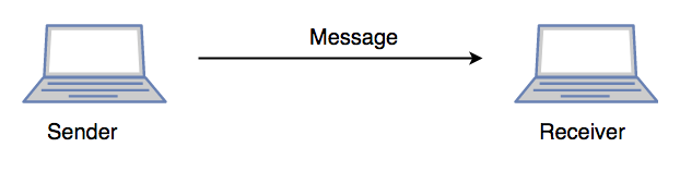
6. Presentation Layer
Presentation layer is also called the Translation layer. The data from the application layer is extracted here and manipulated as per the required format to transmit over the network. The functions of the presentation layer are :
- Translation : For example, ASCII to EBCDIC.
- Encryption/ Decryption : Data encryption translates the data into another form or code. The encrypted data is known as the cipher text and the decrypted data is known as plain text. A key value is used for encrypting as well as decrypting data.
- Compression: Reduces the number of bits that need to be transmitted on the network.
7. Application Layer
At the very top of the OSI Reference Model stack of layers, we find Application layer which is implemented by the network applications. These applications produce the data, which has to be transferred over the network. This layer also serves as a window for the application services to access the network and for displaying the received information to the user.
Ex: Application – Browsers, Skype Messenger etc. >Application Layer is also called as Desktop Layer.
The functions of the Application layer are :
- Network Virtual Terminal
- FTAM-File transfer access and management
- Mail Services
- Directory Services
OSI model acts as a reference model and is not implemented in the Internet because of its late invention. Current model being used is the TCP/IP model.
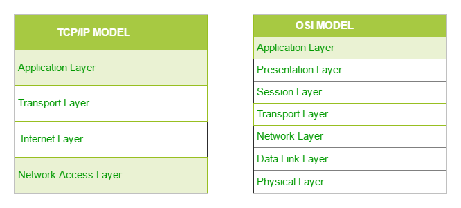
TCP/IP Model
The OSI Model we just looked at is just a reference/logical model. It was designed to describe the functions of the communication system by dividing the communication procedure into smaller and simpler components. But when we talk about the TCP/IP model, it was designed and developed by Department of Defense (DoD) in 1960s and is based on standard protocols. It stands for Transmission Control Protocol/Internet Protocol. The TCP/IP model is a concise version of the OSI model. It contains four layers, unlike seven layers in the OSI model. The layers are:
- Process/Application Layer
- Host-to-Host/Transport Layer
- Internet Layer
- Network Access/Link Layer
The diagrammatic comparison of the TCP/IP and OSI model is as follows :
Difference between TCP/IP and OSI Model:
| TCP/IP | OSI |
|---|---|
| TCP refers to Transmission Control Protocol. | OSI refers to Open Systems Interconnection. |
| TCP/IP has 4 layers. | OSI has 7 layers. |
| TCP/IP is more reliable | OSI is less reliable |
| TCP/IP does not have very strict boundaries. | OSI has strict boundaries |
| TCP/IP follow a horizontal approach. | OSI follows a vertical approach. |
| TCP/IP uses both session and presentation layer in the application layer itself. | OSI uses different session and presentation layers. |
| TCP/IP developed protocols then model. | OSI developed model then protocol. |
| Transport layer in TCP/IP does not provide assurance delivery of packets. | In OSI model, transport layer provides assurance delivery of packets. |
| TCP/IP model network layer only provides connection less services. | Connection less and connection oriented both services are provided by network layer in OSI model. |
| Protocols cannot be replaced easily in TCP/IP model. | While in OSI model, Protocols are better covered and is easy to replace with the change in technology. |
The first layer is the Process layer on the behalf of the sender and Network Access layer on the behalf of the receiver. During this article, we will be talking on the behalf of the receiver.
1. Network Access Layer
This layer corresponds to the combination of Data Link Layer and Physical Layer of the OSI model. It looks out for hardware addressing and the protocols present in this layer allows for the physical transmission of data. We just talked about ARP being a protocol of Internet layer, but there is a conflict about declaring it as a protocol of Internet Layer or Network access layer. It is described as residing in layer 3, being encapsulated by layer 2 protocols.
2. Internet Layer
This layer parallels the functions of OSI’s Network layer. It defines the protocols which are responsible for logical transmission of data over the entire network. The main protocols residing at this layer are :
- IP stands for Internet Protocol and it is responsible for delivering packets from the source host to the destination host by looking at the IP addresses in the packet headers. IP has 2 versions: IPv4 and IPv6. IPv4 is the one that most of the websites are using currently. But IPv6 is growing as the number of IPv4 addresses are limited in number when compared to the number of users.
- ICMP stands for Internet Control Message Protocol. It is encapsulated within IP datagrams and is responsible for providing hosts with information about network problems.
- ARP stands for Address Resolution Protocol. Its job is to find the hardware address of a host from a known IP address. ARP has several types: Reverse ARP, Proxy ARP, Gratuitous ARP and Inverse ARP.
3. Host-to-Host Layer
This layer is analogous to the transport layer of the OSI model. It is responsible for end-to-end communication and error-free delivery of data. It shields the upper-layer applications from the complexities of data. The two main protocols present in this layer are :
- Transmission Control Protocol (TCP) It is known to provide reliable and error-free communication between end systems. It performs sequencing and segmentation of data. It also has acknowledgment feature and controls the flow of the data through flow control mechanism. It is a very effective protocol but has a lot of overhead due to such features. Increased overhead leads to increased cost.
- User Datagram Protocol (UDP) On the other hand does not provide any such features. It is the go-to protocol if your application does not require reliable transport as it is very cost-effective. Unlike TCP, which is connection-oriented protocol, UDP is connectionless.
4. Application Layer
This layer performs the functions of top three layers of the OSI model: Application, Presentation and Session Layer. It is responsible for node-to-node communication and controls user-interface specifications. Some of the protocols present in this layer are: HTTP, HTTPS, FTP, TFTP, Telnet, SSH, SMTP, SNMP, NTP, DNS, DHCP, NFS, X Window, LPD. Have a look at Protocols in Application Layer for some information about these protocols. Protocols other than those present in the linked article are :
- HTTP and HTTPS HTTP stands for Hypertext transfer protocol. It is used by the World Wide Web to manage communications between web browsers and servers. HTTPS stands for HTTP-Secure. It is a combination of HTTP with SSL(Secure Socket Layer). It is efficient in cases where the browser need to fill out forms, sign in, authenticate and carry out bank transactions.
- SSH SSH stands for Secure Shell. It is a terminal emulations software similar to Telnet. The reason SSH is more preferred is because of its ability to maintain the encrypted connection. It sets up a secure session over a TCP/IP connection.
- NTP NTP stands for Network Time Protocol. It is used to synchronize the clocks on our computer to one standard time source. It is very useful in situations like bank transactions. Assume the following situation without the presence of NTP. Suppose you carry out a transaction, where your computer reads the time at 2:30 PM while the server records it at 2:28 PM. The server can crash very badly if it’s out of sync.
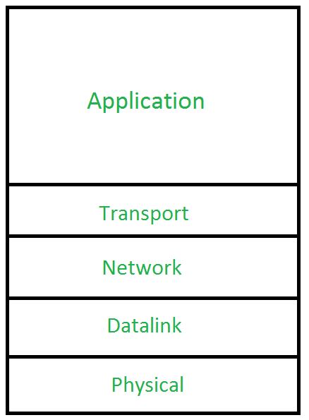
Hybrid model
Layered Internet protocol stack
In the real world, we use a mix of both the OSI model and the TCP/IP model, called the Hybrid model. In the Hybrid model, the Application layer is a combination of layer 7, layer 6 and layer 5 of OSI model (similar to TCP/IP model). The remaining layers (layer 1, 2, 3 and 4) are the same as the OSI model.
application: supporting network applications
- HTTP, IMAP, SMTP, DNS
transport: process-process data transfer
- TCP, UDP
network: routing of datagrams from source to destination
- IP, routing protocols
link: data transfer between neighboring network elements
- Ethernet, 802.11 (Wi-Fi), PPP
physical: bits “on the wire”
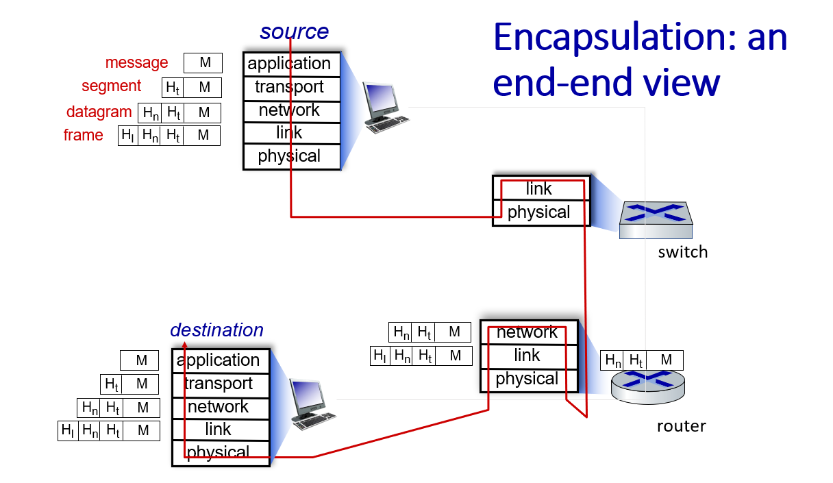
Services, Layering and Encapsulation
Watch the courseware and instructional videos for more details.
1.6 Basic Network Attacks in Computer Network
Networks Under Attack
Many people rely on the Internet for many of their professional, social and personal activities. But there are also people who attempt to damage our Internet-connected computers, violate our privacy and render inoperable the Internet services.
Given the frequency and variety of existing attacks as well as the threat of new and more destructive future attacks, network security has become a central topic in the field of computer networking.
How are computer networks vulnerable? What are some of the more prevalent types of attacks today?
Malware – short for malicious software which is specifically designed to disrupt, damage, or gain authorized access to a computer system. Much of the malware out there today is self-replicating: once it infects one host, from that host it seeks entry into other hosts over the Internet, and from the newly infected hosts, it seeks entry into yet more hosts. In this manner, self-replicating malware can spread exponentially fast.
Virus – A malware which requires some form of user’s interaction to infect the user’s device. The classic example is an e-mail attachment containing malicious executable code. If a user receives and opens such an attachment, the user inadvertently runs the malware on the device.
Worm – A malware which can enter a device without any explicit user interaction. For example, a user may be running a vulnerable network application to which an attacker can send malware. In some cases, without any user intervention, the application may accept the malware from the Internet and run it, creating a worm.
Botnet – A network of private computers infected with malicious software and controlled as a group without the owners’ knowledge, e.g. to send spam.
DoS (Denial of Service) – A DoS attack renders a network, host, or other pieces of infrastructure unusable by legitimate users. Most Internet DoS attacks fall into one of three categories :
• Vulnerability attack: This involves sending a few well-crafted messages to a vulnerable application or operating system running on a targeted host. If the right sequence of packets is sent to a vulnerable application or operating system, the service can stop or, worse, the host can crash.
• Bandwidth flooding: The attacker sends a deluge of packets to the targeted host—so many packets that the target’s access link becomes clogged, preventing legitimate packets from reaching the server.
• Connection flooding: The attacker establishes a large number of half-open or fully open TCP connections at the target host. The host can become so bogged down with these bogus connections that it stops accepting legitimate connections.
DDoS (Distributed DoS) – DDoS is a type of DOS attack where multiple compromised systems, are used to target a single system causing a Denial of Service (DoS) attack. DDoS attacks leveraging botnets with thousands of comprised hosts are a common occurrence today. DDoS attacks are much harder to detect and defend against than a DoS attack from a single host.
Packet sniffer – A passive receiver that records a copy of every packet that flies by is called a packet sniffer. By placing a passive receiver in the vicinity of the wireless transmitter, that receiver can obtain a copy of every packet that is transmitted! These packets can contain all kinds of sensitive information, including passwords, social security numbers, trade secrets, and private personal messages. some of the best defenses against packet sniffing involve cryptography.
IP Spoofing – The ability to inject packets into the Internet with a false source address is known as IP spoofing, and is but one of many ways in which one user can masquerade as another user. To solve this problem, we will need end-point authentication, that is, a mechanism that will allow us to determine with certainty if a message originates from where we think it does.
Man-in-the-Middle Attack – As the name indicates, a man-in-the-middle attack occurs when someone between you and the person with whom you are communicating is actively monitoring, capturing, and controlling your communication transparently. For example, the attacker can re-route a data exchange. When computers are communicating at low levels of the network layer, the computers might not be able to determine with whom they are exchanging data.
Compromised-Key Attack – A key is a secret code or number necessary to interpret secured information. Although obtaining a key is a difficult and resource-intensive process for an attacker, it is possible. After an attacker obtains a key, that key is referred to as a compromised key. An attacker uses the compromised key to gain access to a secured communication without the sender or receiver being aware of the attack.
Phishing – The fraudulent practice of sending emails purporting to be from reputable companies in order to induce individuals to reveal personal information, such as passwords and credit card numbers.
DNS spoofing – Also referred to as DNS cache poisoning, is a form of computer security hacking in which corrupt Domain Name System data is introduced into the DNS resolver’s cache, causing the name server to return an incorrect IP address.
再也不用英文做笔记了。。。。。复习发现根本看不懂
Reference
- http://gaia.cs.umass.edu/kurose_ross/index.html ↩︎
- https://www.whoismyisp.org/articles/what-is-an-isp ↩︎
- https://www.differencebetween.com/difference-between-throughput-and-vs-bandwidth/ ↩︎
- Speed vs Bandwidth Explained - Arvig ↩︎
- https://speed.cloudflare.com/ ↩︎
- https://www.geeksforgeeks.org/layers-of-osi-model/ ↩︎